YAMAHA FS1 1969
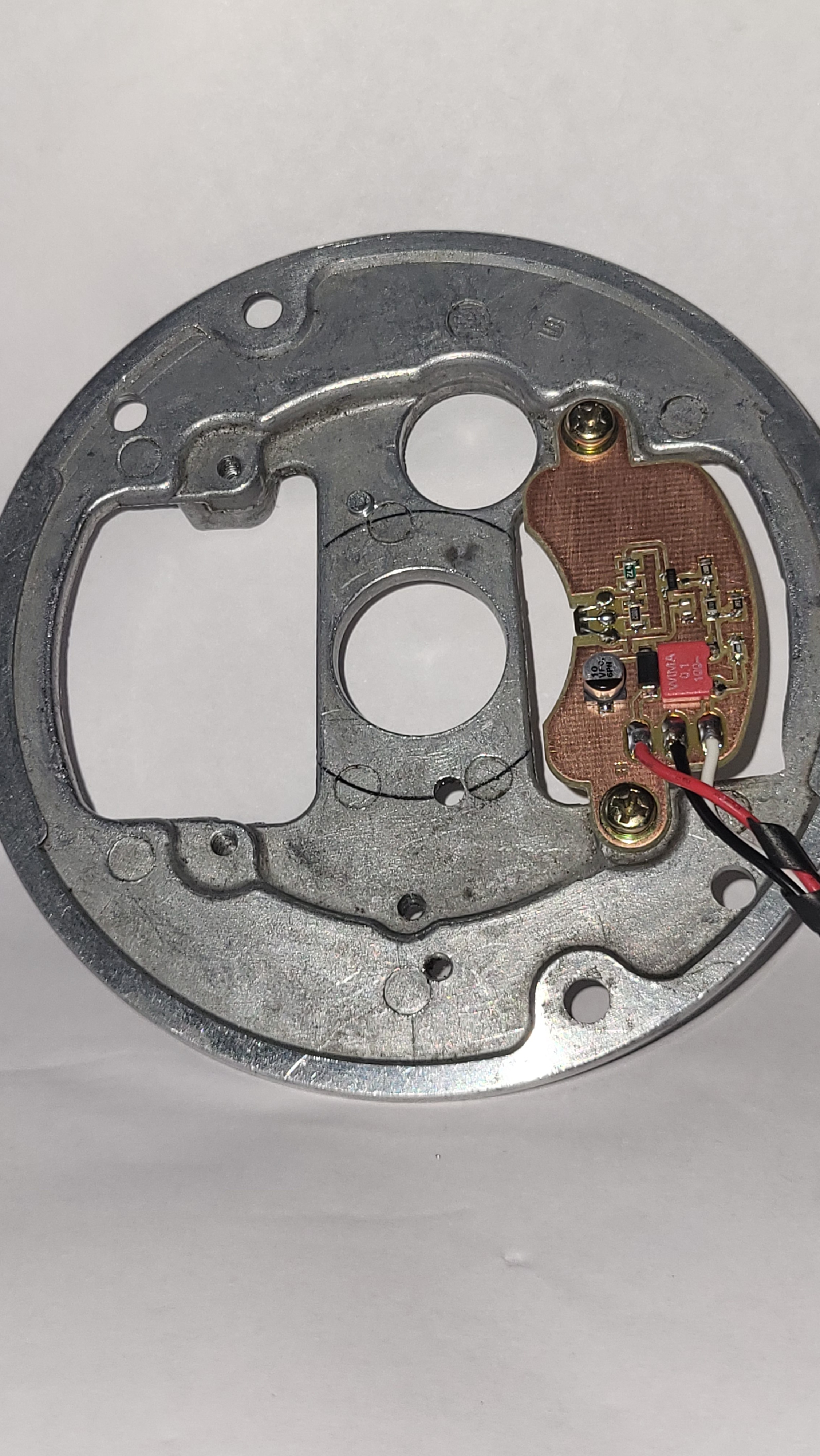
The small PCB is mounted on the rear side of the Stator Plate
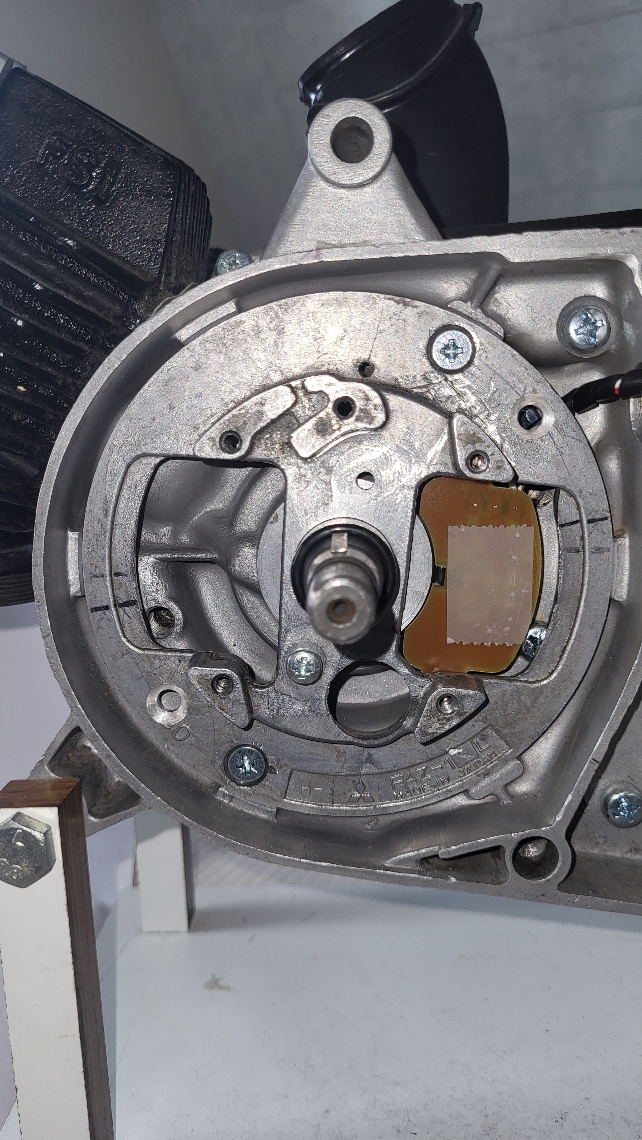
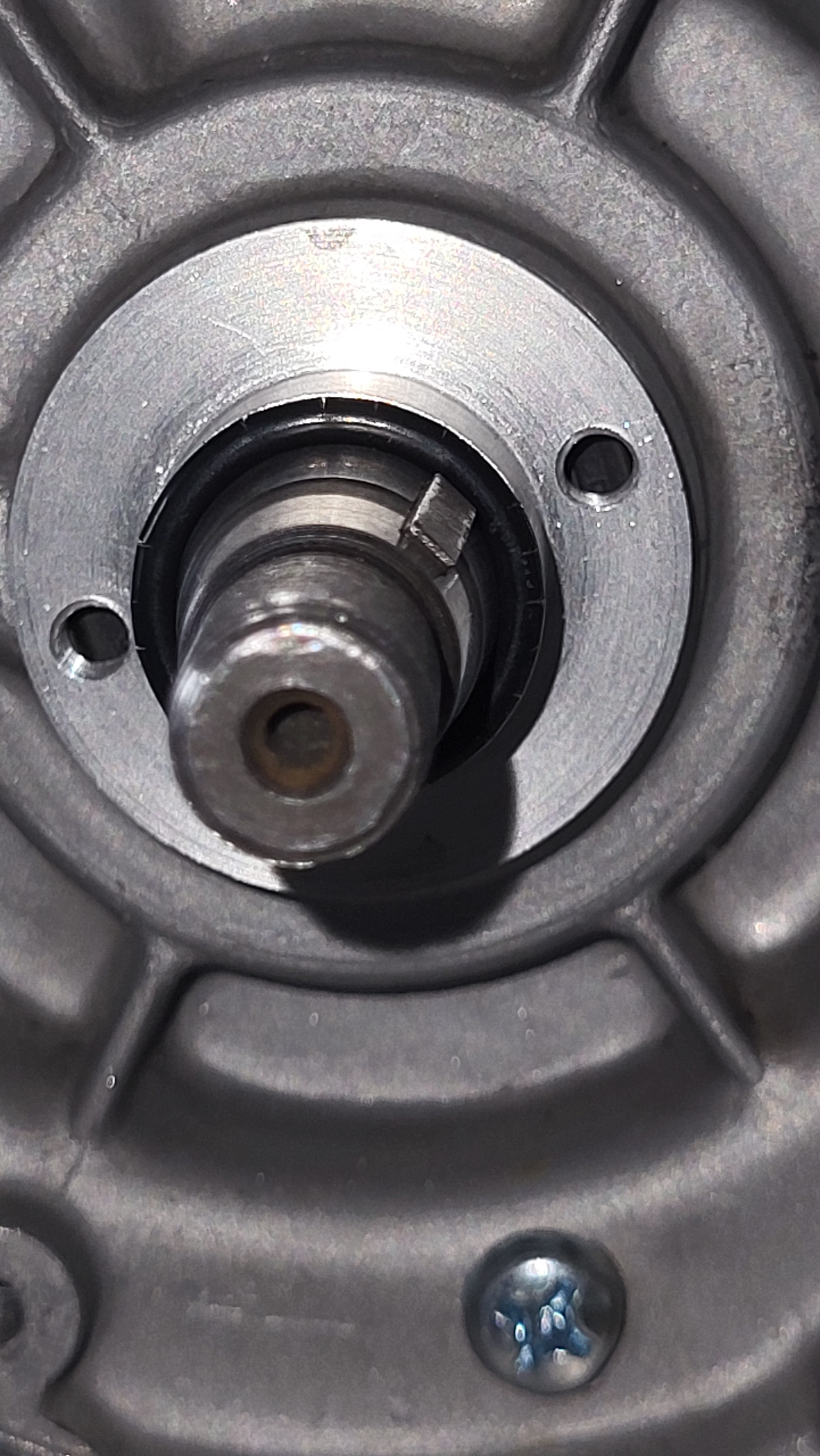
Rear side of the Stator Plate with the crankshaft Pulser
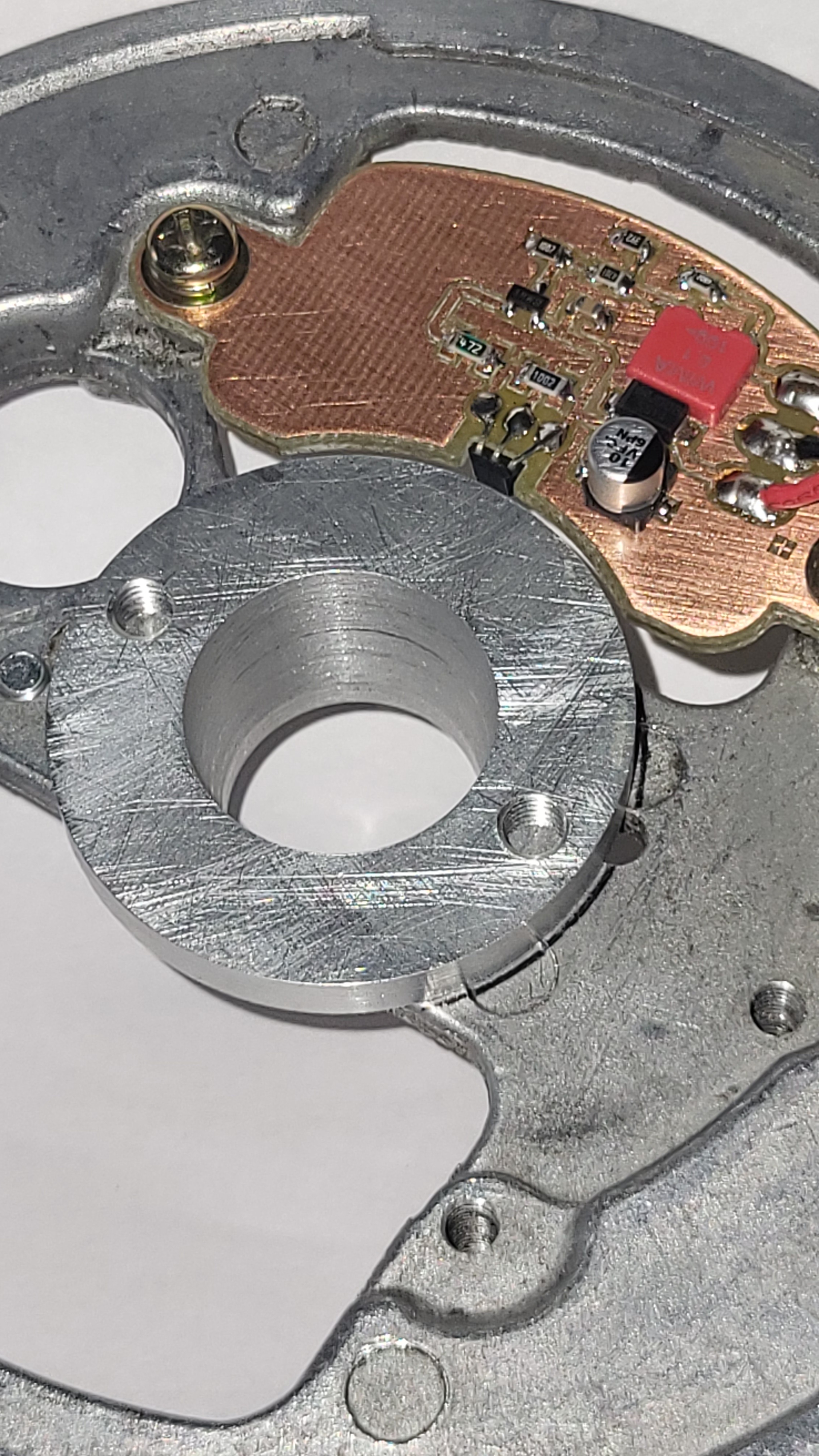
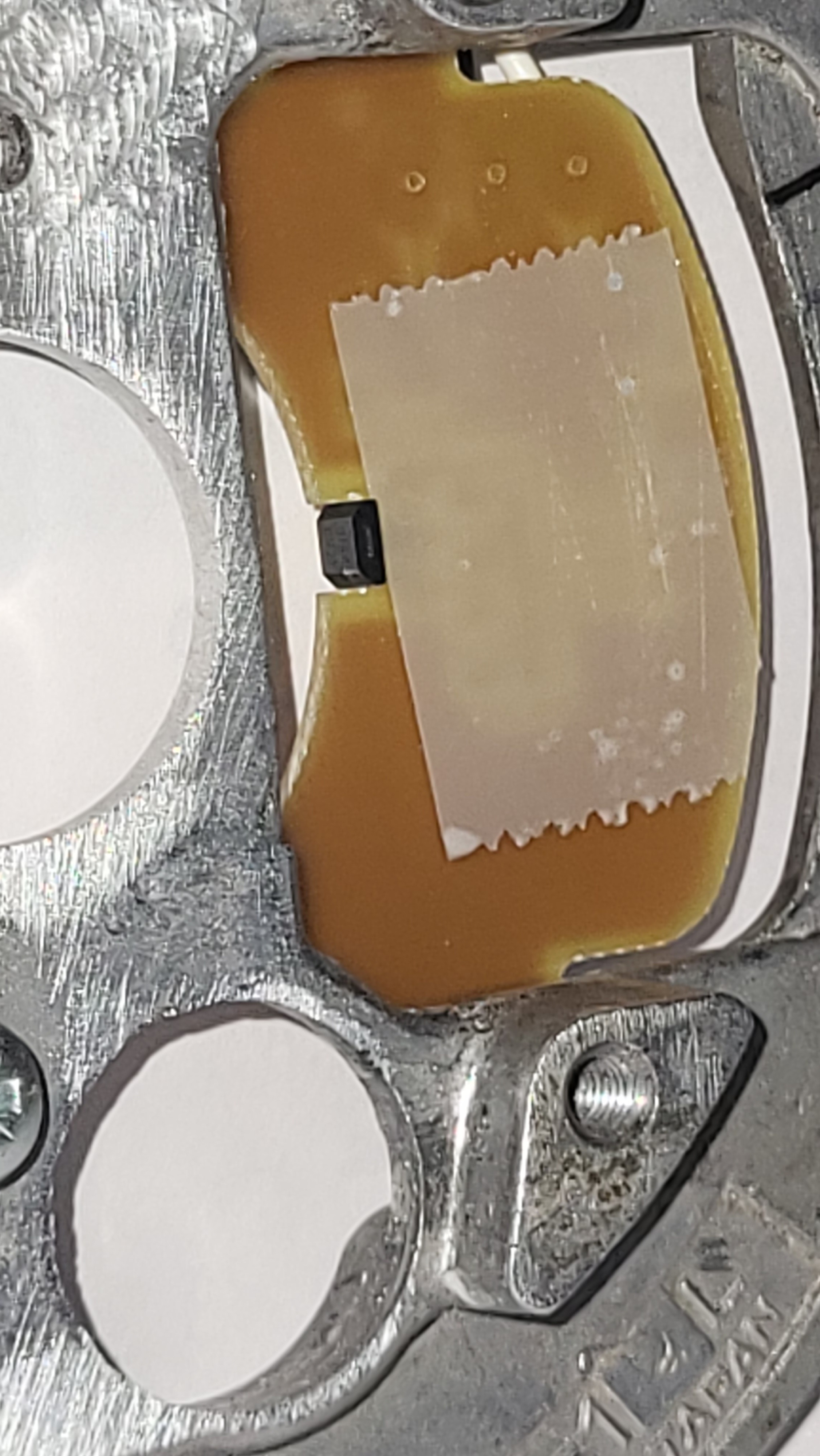
PCB with the small Hall Effect sensor
Another approach is using the 'empty capacitor space' for a 3D printed Hall sensor fitting with a small pcb on top.
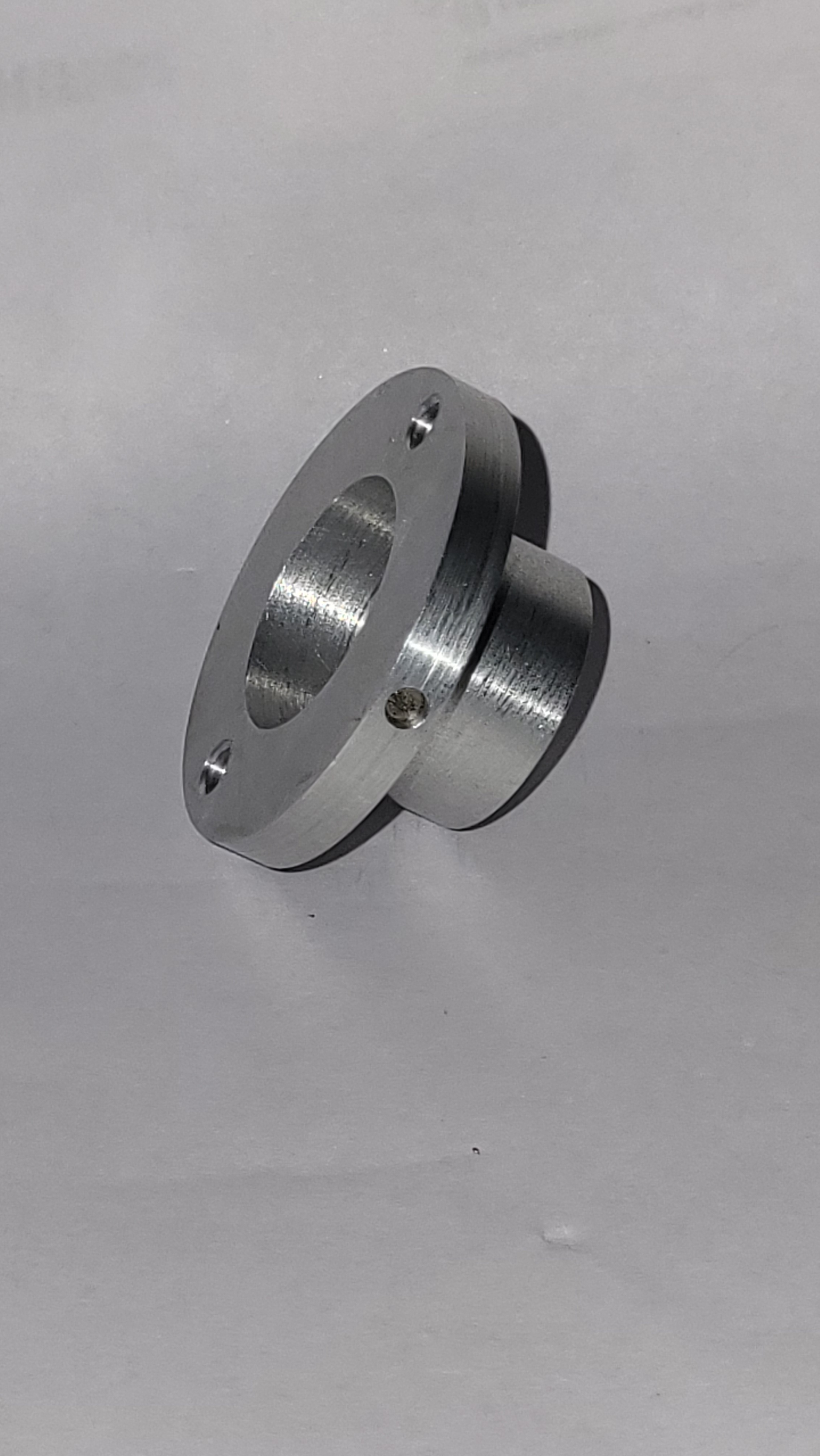
O-ring fitted between flywheel and crankshaft pulser to keep it tight
The inserted 3mm magnet
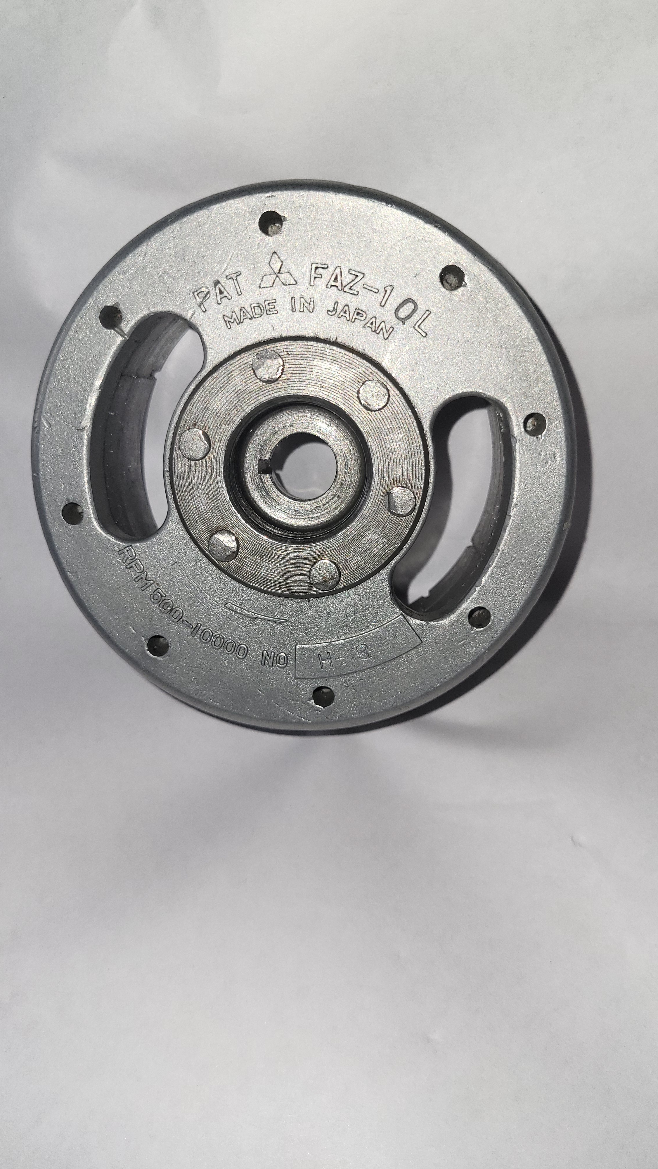
The original 1969 Flywheel
Everything mounted together with the Pulser and PCB behind the stator plate
The lightning coil uses the same threaded holes
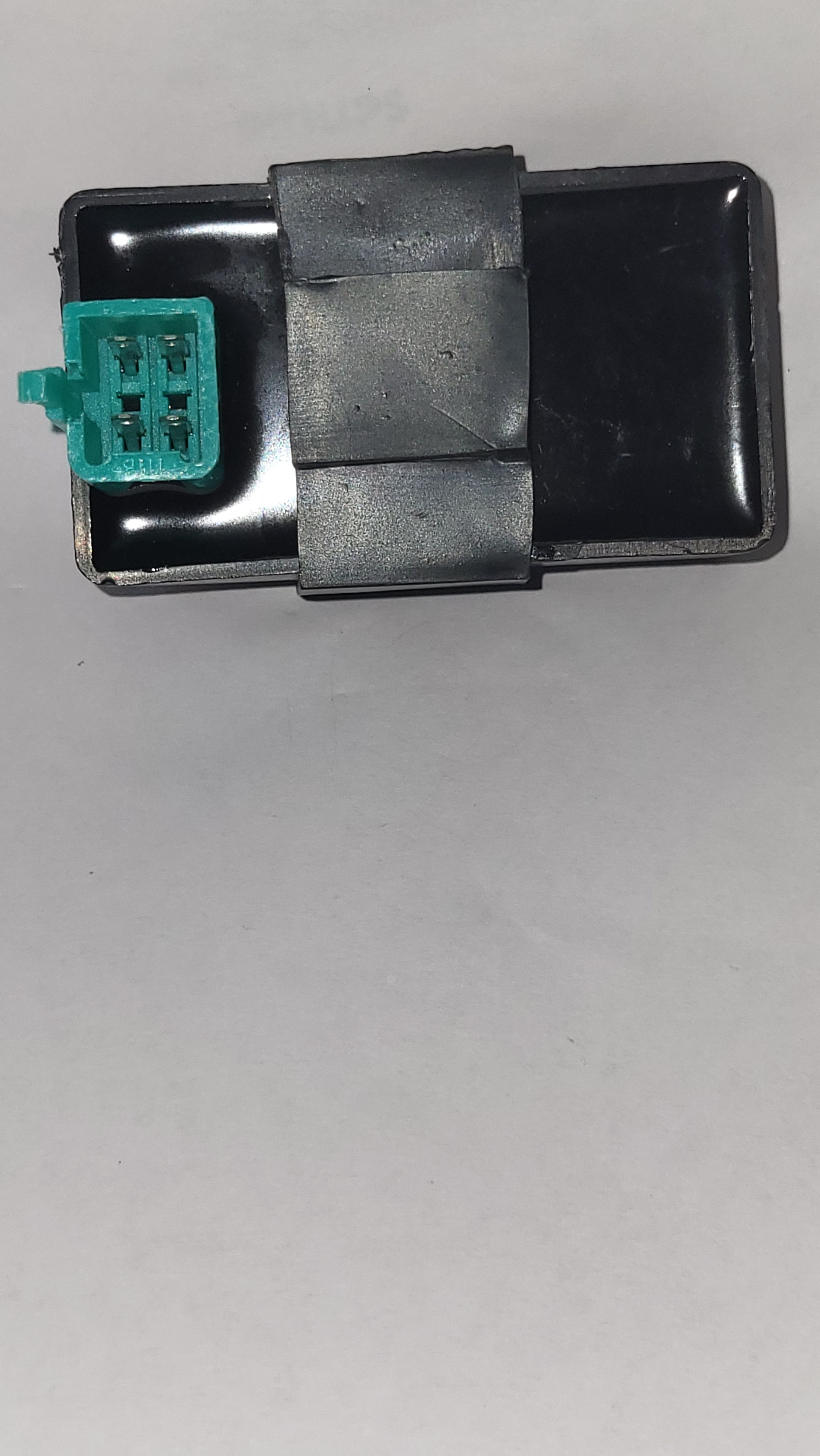
The used DC CDI unit
I used the old, standard, 6Volt battery housing for a new 12V powersupply.
First I cut off the top section with a small hacksaw and removed the lead segments inside.
After that I removed the 'segment Guiding rails' to create a clean inside box.
The new battery consists of a batteryholder with two Lithium-ion batteries, giving it a total of 7.2Volt. I also installed a 2-cell BMS for battery protection to prevent undervoltage. The batteries are 3000mA 18650 type.
This is all fitted inside the old battery housing protectec with some foam.
To power the 12Volt CDI unit I used a Boost/Buck converter to crankup the 7.2 voltage to 12V.
For the charging you can use a simple Aliexpress Li-Ion charging pcb with a Bridge Rectifier and a Capacitor, about 4700uF/35v